

 Current location:
NEWS INFORMATION
Thin-Wall Aluminum Die Casting: How Far the Wall Can Go
date:2026-09-24 15:06:14 click:65
Every lightweighting conversation eventually arrives at the same question: how thin can the wall be? The honest answer from a production floor is less exciting than the laboratory number. A wall of 1 mm is possible on a small part under ideal gating, and 0.6 mm has been demonstrated in trials. Neither figure is what a supplier will quote for a structural component that has to survive assembly, coating and ten years of service. What matters more is understanding the relationship between wall thickness, how far the metal has to travel, and the defects that appear when that relationship is pushed.
What "Thin Wall" Means in a Quote
In commercial production, 2.0 to 2.5 mm is the working range for medium-sized aluminum parts, 1.5 mm appears on smaller components with short flow paths, and anything below roughly 1.2 mm moves into specialist territory with a yield penalty attached. The penalty is real: thinner sections mean faster heat loss during fill, which means the metal front can freeze before the cavity completes. Yield drops, cycle time does not improve as much as expected, and the unit price rises even though the part weighs less. A thin wall that increases scrap from 3 percent to 12 percent has not saved anything.
Flow Length Is the Constraint Everyone Forgets
Designers look at wall thickness; foundries look at the ratio of flow length to wall thickness. A 2 mm wall is comfortable if the metal travels 80 mm to reach the furthest corner, and marginal if it travels 400 mm. This is why large flat panels with thin walls are genuinely difficult, and why housings for electronics often use a slightly thicker wall with a rib network instead of a uniformly thin shell. When a part is simply too large for the desired thickness, the practical options are multiple gates fed from different sides, a redesign that shortens the distance metal must travel, or an acceptance that the wall needs another half millimetre. Asking a casting manufacturer for a fill simulation output early is the cheapest way to find out which situation applies.
Ribs, Bosses and Local Thickening
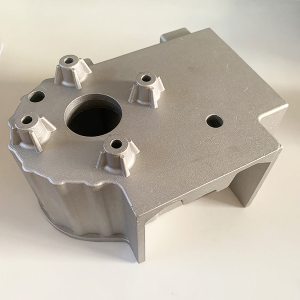
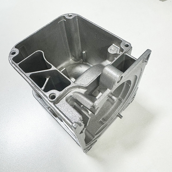
Thin walls need ribs for stiffness, and ribs create their own problem: every rib is a place where metal accumulates and cools slowly, which produces sink marks on the opposite face. Keeping rib thickness at around 60 to 70 percent of the wall thickness, with a fillet radius at the root, is the standard mitigation. Bosses for screws are worse because they are essentially local lumps. The fix is to design the boss as a ring connected to the wall by ribs rather than a solid cylinder sitting on a plate, which keeps section thickness roughly uniform and dramatically reduces sink.
Defects That Thin Walls Invite
Cold shuts — where two metal fronts meet without fusing — are the signature thin-wall defect, and they show up as a visible line that also happens to be a crack path. Misruns leave the cavity unfilled. Both are thermal problems: either the metal lost too much heat, or the die was too cold at that zone, or the fill took too long. Raising metal temperature helps a little; raising die temperature in the problem zone helps more; increasing injection speed helps most but brings air entrapment with it. Vacuum assistance is the standard way to get speed without porosity, and it is the single upgrade that most expands what thin-wall production can do.
Alloy and Process Adjustments
Higher silicon improves fluidity, which is why AlSi9Cu3 fills thin sections more reliably than a low-silicon structural alloy, and why there is a genuine tension between castability and mechanical properties in thin-wall design. Where ductility is required, vacuum casting plus careful thermal management becomes mandatory rather than optional. Squeeze pins at locally thick areas reduce shrinkage voids. Die coatings and release agents affect heat transfer enough to change fill behaviour, which is one reason a process that runs beautifully for one shift can start producing cold shuts after a spray setting is changed.
When a Thicker Wall Is the Right Answer
Sometimes the answer is to stop pushing. If a part needs to carry impact loads, hold a press-fit, survive a thread being tapped, or resist corrosion over a long service life, thickness is cheap insurance. Machining also removes material, so a thin wall with a machined sealing face may end up thinner at the critical location than the drawing suggests. And a wall below about 1.5 mm makes porosity proportionally more damaging: a 0.3 mm void in a 2 mm wall is a 15 percent section loss, while in a 4 mm wall it is 7 percent. Lightweighting by geometry — better rib layout, removal of unused material, combining parts — often beats simply thinning everything.
What to Ask Before Committing
Bring the 3D model, target wall thickness, annual volume, mechanical requirements and any cosmetic standard. Ask the supplier for its standard minimum wall at the part's flow length, whether the machine has vacuum capability, and whether fill simulation is part of the tooling package. Then ask the question that separates an experienced factory from an optimistic one: at that wall thickness, what yield does it expect in steady production? A supplier willing to name a number is one that has actually run thin-wall work.
References
North American Die Casting Association. (2018). NADCA Product Specification Standards for Die Castings (S-4P-2018). NADCA.
ASM International. (2008). ASM Handbook, Volume 15: Casting. ASM International.
ASTM International. (2018). ASTM B85/B85M: Standard Specification for Aluminum-Alloy Die Castings. ASTM International.
ASTM International. (2016). ASTM B557/B557M: Standard Test Methods for Tension Testing Wrought and Cast Aluminum- and Magnesium-Alloy Products. ASTM International.
International Organization for Standardization. (2019). ISO 6892-1: Metallic materials - Tensile testing - Part 1: Method of test at room temperature. ISO.
Aluminum Association. (2020). Aluminum Standards and Data. The Aluminum Association.






Botou Ruitai Die Casting Co., Ltd.
Copyright © 2026-202 https://www.ruitaidiecasting.com. All Rights Reserved Botou Ruitai Die Casting Co., Ltd.All rights reserved