

 Current location:
NEWS INFORMATION
Precision and Tolerance in Die Casting: Achieving Dimensional Accuracy
date:2026-08-27 16:30:37 click:90
How accurate can a die casting actually be? The answer depends on who you ask and what part you are making. Die casting is a high-precision process compared to sand casting, but it is not CNC machining. Understanding what tolerances are realistic, and where machining becomes necessary, keeps your project on budget and your supplier honest. This article explains the factors that control dimensional accuracy in die cast parts and how to specify them correctly.
What Tolerance Can Die Casting Actually Hold?
As a rough rule, commercial die castings hold around plus or minus 0.1 mm per 25 mm for aluminum, with zinc doing a bit better. Small features can hold tighter; large dimensions across a big part hold looser. The real numbers depend on the alloy, the part geometry, and the condition of the die. Standards such as ISO 8062-3 and the NADCA Product Specification Standards give tolerance classes for molded parts, which is a useful starting point when you write your drawing. Note that tolerances also drift as the die wears, so a supplier's process should include periodic checks that catch wear before parts go out of spec.
Draft Angles and Parting Lines
Two geometric realities shape every die casting. First, draft: walls must be slightly tapered so the part releases from the die. Typical draft is 1 to 2 degrees. Without it, the part sticks, the die wears, and the surface gets dragged. Second, the parting line: the seam where the two die halves meet. Tolerances across the parting line are harder to hold than within one die half, because any mismatch or wear shows up as a step on the finished part.
Shrinkage and Thermal Effects
Molten aluminum shrinks about 0.5 to 0.7 percent as it cools and solidifies. The die is designed with that shrinkage factored in, but shrinkage is never perfectly uniform. Sections that cool at different rates distort slightly, so a large thin part may come out flatter or more bowed than drawn. Warpage is a tolerance issue that no amount of machining can fully fix. It is addressed in design and process, which is another reason to involve the manufacturer early.
When Machining Makes Sense
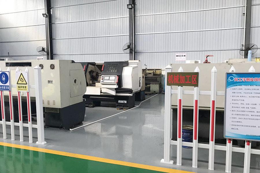
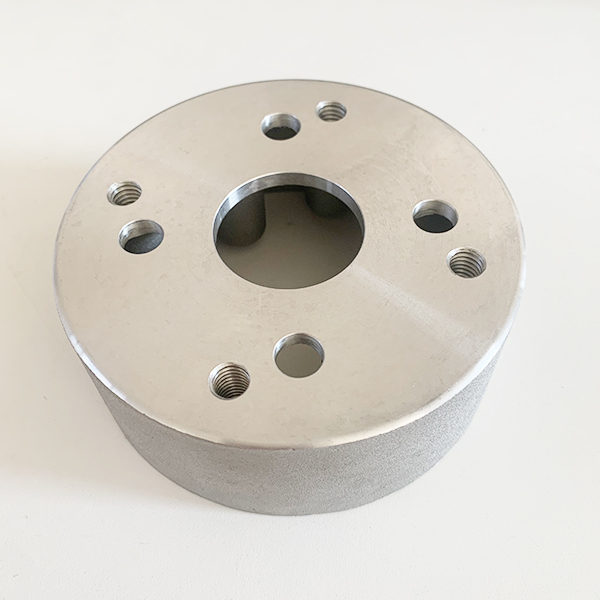
Some features should simply be machined. Threaded holes, precise bores, sealing faces, and surfaces that mate with other components routinely go through CNC after casting. Machining also removes the as-cast surface layer, which matters for pressure-tight applications where surface porosity could leak. A sensible split: let the casting do the gross geometry, let machining do the fine geometry, and let the drawing say which is which. That division of labor keeps cost down and quality up.
How to Specify Tolerances on Your Drawing
Resist the urge to put tight tolerances everywhere. Every tight dimension adds cost, because the supplier must hold it, measure it, and reject parts that miss it. Mark only the functional dimensions as critical, use standard tolerance classes for the rest, and note the datum structure clearly. A drawing that separates critical and general tolerances is easier to quote and cheaper to produce. Suppliers appreciate drawings that tell them what really matters.
Measuring and Verifying Accuracy
Inspection methods range from simple calipers and pin gauges to coordinate measuring machine programs that check dozens of points automatically. For critical features, CMM gives the definitive answer. Radiography and sectioning check internal soundness, which surface measurements cannot see. Ask your supplier what they measure, how often, and whether the records survive an audit. A factory that can show you measurement data from last month's production run is a factory you can trust with next month's order. If the factory offers to send inspection data with every shipment, take them up on it; that habit alone tells you a lot about how they run the floor.
Common Tolerance Mistakes Buyers Make
Three mistakes come up constantly. The first is applying tight tolerances to every dimension on the drawing, which inflates cost and inspection time for features that do not need it. The second is ignoring the parting line and draft when setting tolerances, so the supplier has to hold numbers that the process cannot reliably deliver at that location. The third is changing tolerances after the tool is cut. A late tolerance change usually means die modification, which costs money and weeks of schedule. The fix for all three is the same: review the drawing with the manufacturer before tooling, agree on which dimensions are truly critical, and put that agreement in writing. A small amount of discipline at the start of a project saves a disproportionate amount of pain at the end.
References
ISO 8062-3:2007, Geometrical product specifications — Dimensional and geometrical tolerances for moulded parts.
North American Die Casting Association, Product Specification Standards for Die Castings.
ASM International, ASM Handbook, Volume 15: Casting.
ISO 1101:2017, Geometrical product specifications — Geometrical tolerancing.
ASTM International, ASTM E505, Standard Reference Radiographs for Inspection of Aluminum and Magnesium Die Castings.






Botou Ruitai Die Casting Co., Ltd.
Copyright © 2026-202 https://www.ruitaidiecasting.com. All Rights Reserved Botou Ruitai Die Casting Co., Ltd.All rights reserved